Privacy statement: Your privacy is very important to Us. Our company promises not to disclose your personal information to any external company with out your explicit permission.
Model No.: YZPST-BD139
Brand: YZPST
Productivity: 1000
Transportation: Ocean,Air
Place of Origin: China
Supply Ability: 10000
Certificate: ISO9001-2008,ROHS
HS Code: 85413000
Port: SHANGHAI
Payment Type: L/C,T/T,Paypal
Incoterm: FOB,CFR,CIF
Complementary low voltage transistor
YZPST-BD139
Features
■ Products are pre-selected in DC current gain
Application
■ General purpose
Description
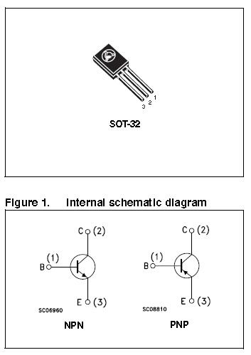
These epitaxial planar transistors are mounted in the SOT-32 plastic package. They are designed for audio amplifiers and drivers utilizing complementary or quasi-complementary circuits. The NPN types are the BD135 and BD139, and the complementary PNP types are the BD136 and BD140.
Table 1. Device summary
| Order codes | Marking | Package | Packaging |
| BD135 | BD135 |
SOT-32 |
Tube |
| BD135-16 | BD135-16 | ||
| BD136 | BD136 | ||
| BD136-16 | BD136-16 | ||
| BD139 | BD139 | ||
| BD139-10 | BD139-10 | ||
| BD139-16 | BD139-16 | ||
| BD140 | BD140 | ||
| BD140-10 | BD140-10 | ||
| BD140-16 | BD140-16 |
Table 2. Absolute maximum ratings
|
Symbol |
Parameter | Value |
Unit | |||
| NPN | PNP | |||||
| BD135 | BD139 | BD136 | BD140 | |||
| VCBO | Collector-base voltage (IE = 0) | 45 | 80 | -45 | -80 | V |
| VCEO | Collector-emitter voltage (IB = 0) | 45 | 80 | -45 | -80 | V |
| VEBO | Emitter-base voltage (IC = 0) | 5 | -5 | V | ||
| IC | Collector current | 1.5 | -1.5 | A | ||
| ICM | Collector peak current | 3 | -3 | A | ||
| IB | Base current | 0.5 | -0.5 | A | ||
| PTOT | Total dissipation at Tc ≤ 25 °C | 12.5 | W | |||
| PTOT | Total dissipation at Tamb ≤ 25 °C | 1.25 | W | |||
| Tstg | Storage temperature | -65 to 150 | °C | |||
| Tj | Max. operating junction temperature | 150 | °C | |||
Table 3. Thermal data
| Symbol | Parameter | Max value | Unit |
| Rthj-case | Thermal resistance junction-case | 10 | °C/W |
| Rthj-amb | Thermal resistance junction-ambient | 100 | °C/W |
| ||||||||||||||||||||||||||||||||||||||||||||||||||||||||||||||||||||||||||||||||||||||||||||||||||||||||||||||
Table 4. On/off states
|
Symbol |
Parameter |
Polarity |
Test conditions | Value |
Unit | ||
| Min. | Typ. | Max. | |||||
|
ICBO |
Collector cut-off current (I =0) |
NPN | VCB = 30 V VCB = 30 V, TC = 125 °C |
|
| 0.1 10 | µA µA |
|
PNP | VCB = -30 V VCB = -30 V, TC = 125 °C |
|
| -0.1 -10 | µA µA | ||
|
IEBO | Emitter cut-off current (I =0) | NPN | VEB = 5 V |
|
| 10 | µA |
| PNP | VEB = -5 V |
|
| -10 | µA | ||
|
VCEO(sus)(1) |
Collector-emitter sustaining voltage (IB=0) |
NPN | IC = 30 mA BD135 BD139 |
45 80 |
|
|
V V |
|
PNP | IC = -30 mA BD136 BD140 |
-45 -80 |
|
|
V V | ||
|
VCE(sat) (1) |
Collector-emitter saturation voltage | NPN | IC = 0.5 A, IB = 0.05 A |
|
| 0.5 | V |
| PNP | IC = -0.5 A, IB = -0.05 A |
|
| -0.5 | V | ||
|
VBE (1) |
Base-emitter voltage | NPN | IC = 0.5 A, VCE = 2 V |
|
| 1 | V |
| PNP | IC = -0.5 A, VCE = -2 V |
|
| -1 | V | ||
|
hFE (1) |
DC current gain |
NPN | IC = 5 mA, VCE = 2 V IC = 150 mA, VCE = 2 V IC = 0.5 A, VCE = 2 V | 25 40 25 |
|
250 |
|
|
PNP | IC = -5 mA, VCE = -2 V IC = -150 mA, VCE = -2 V IC = -0.5 A, VCE = -2 V | 25 40 25 |
|
250 |
| ||
|
hFE (1) |
hFE groups |
NPN | IC = 150 mA, VCE = 2 V BD139-10 BD135-16/BD139-16 |
63 100 |
|
160 250 |
|
|
PNP | IC = -150 mA, VCE = -2 V BD140-10 BD136-16/BD140-16 |
63 100 |
|
160 250 |
| ||


Product Categories : Semiconductor Plastic Package > Silicon Transistor


Privacy statement: Your privacy is very important to Us. Our company promises not to disclose your personal information to any external company with out your explicit permission.

Fill in more information so that we can get in touch with you faster
Privacy statement: Your privacy is very important to Us. Our company promises not to disclose your personal information to any external company with out your explicit permission.